Steel Structure Design Process: From Concept to Shop Drawings
Steel Structure Design Process: From Concept to Shop Drawings is a comprehensive journey that transforms initial ideas into precise, buildable plans for durable steel buildings.
This process ensures safety, efficiency, and compliance with industry standards, making it essential for engineers, architects, and clients in modern construction projects. Steel Structure Design Process: From Concept to Shop Drawings involves meticulous planning and technical expertise to deliver structures that withstand real-world demands.
Inputs Needed Before Starting the Structural Design
Steel Structure Design Process: From Concept to Shop Drawings begins with gathering critical inputs to lay a solid foundation for the entire project.
These inputs include site-specific data, architectural plans, and preliminary load estimates, which guide engineers in creating feasible designs.
Without accurate inputs, even the most advanced analysis tools can lead to costly revisions later in the Steel Structure Design Process: From Concept to Shop Drawings.
Essential inputs encompass geotechnical reports detailing soil bearing capacity, groundwater levels, and seismic zone classifications. Clients must provide building usage details, such as whether the structure will house industrial equipment, offices, or warehouses, influencing material selections and safety factors. Environmental data like local wind speeds and snow loads are also vital, often sourced from building codes such as ASCE 7 or Eurocode standards.
Furthermore, regulatory requirements form key inputs, including zoning laws, fire safety codes, and sustainability mandates that dictate material grades and insulation needs.
Budget constraints and timelines are non-technical but crucial inputs, helping prioritize cost-effective solutions without compromising integrity.
In the Steel Structure Design Process: From Concept to Shop Drawings, digital tools like BIM software integrate these inputs early, enabling clash detection and streamlined collaboration among stakeholders.
Architectural drawings provide dimensional inputs, specifying column grids, floor heights, and opening locations that shape the structural skeleton.
Mechanical, electrical, and plumbing (MEP) layouts are reviewed to avoid interferences, ensuring the Steel Structure Design Process: From Concept to Shop Drawings accounts for all building systems holistically. Historical data from similar projects refines inputs, drawing on past performance to anticipate challenges like corrosion in coastal areas.
Preliminary cost estimates based on these inputs help validate project viability before full commitment. Engineers often conduct value engineering sessions to optimize inputs, balancing performance with economics.
Thus, robust inputs ensure the Steel Structure Design Process: From Concept to Shop Drawings progresses smoothly from ideation to execution, minimizing risks and enhancing project outcomes.
read: Fire-Rated Steel Buildings: Standards, Materials & Best Practices
Load Considerations: Dead, Live, Wind, Seismic, and Equipment Loads
Steel Structure Design Process: From Concept to Shop Drawings relies heavily on accurate load considerations to guarantee structural integrity under diverse conditions.
Dead loads represent permanent weights like the steel framework itself, roofing, and fixed finishes, calculated using material densities and component volumes. Live loads vary by occupancy, such as crowds in arenas or stored goods in warehouses, per codes like IBC or BS 6399.
Wind loads demand dynamic analysis, factoring in building shape, height, terrain exposure, and gust factors to prevent uplift or sway.
Seismic loads require response spectrum analysis in earthquake-prone regions, considering soil-structure interaction and ductility demands on steel members.
Equipment loads from cranes, HVAC units, or machinery introduce point or distributed forces, often the most unpredictable in industrial settings.
In the Steel Structure Design Process: From Concept to Shop Drawings, load combinations per LRFD or ASD methods amplify these effects—factoring dead loads at 1.2, live at 1.6, wind at 0.5-1.0, and seismic similarly—to simulate worst-case scenarios. Software like ETABS or SAP2000 models these loads precisely, outputting internal forces for member sizing.
Snow and rain loads add to vertical demands, especially in sloped roofs, while temperature-induced expansions necessitate movement joints.
Vibration from rotating equipment or foot traffic influences fatigue checks, extending the Steel Structure Design Process: From Concept to Shop Drawings to serviceability limits like deflection ratios of L/360 for floors.
Clients benefit from understanding these considerations, as they inform foundation design and bracing needs. Proper load documentation in reports ensures compliance and facilitates insurance approvals.
Ultimately, meticulous load considerations elevate the Steel Structure Design Process: From Concept to Shop Drawings, yielding resilient structures that perform reliably over decades.
Concept Design: Grid, Spans, Height, and Stability System
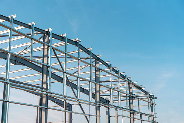
Steel Structure Design Process: From Concept to Shop Drawings advances through concept design, where grid layouts, spans, heights, and stability systems take shape.
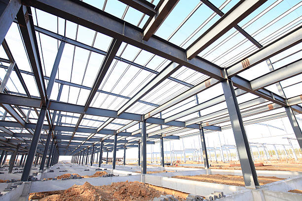
The grid defines column spacing, typically 6-12 meters for efficiency, optimizing material use while accommodating functional layouts like production lines or parking bays. Spans influence economy—longer clear spans up to 50 meters suit pre-engineered buildings (PEBs) using trusses or moment frames.
Building height dictates lateral systems; low-rise structures under 20 meters favor braced frames, while taller ones employ shear walls or outriggers.
Stability systems combat buckling and sway, selecting from concentric bracing (cheaper, stiffer) or eccentric for ductility. In the Steel Structure Design Process: From Concept to Shop Drawings, preliminary sketches iterate options, balancing aesthetics, cost, and code compliance.
Architectural inputs refine the concept, aligning grids with facades and ensuring spans match interior partitions. Software sketches 3D models early, visualizing massing and simulating wind tunnel effects virtually. Economy guides choices—rigid frames for single-story portals excel in simplicity and speed.
Stability systems integrate vertical bracing in X, K, or chevron patterns along perimeters and cores, sized via preliminary analysis. Portal frames suit simple sheds, while multi-bay grids need cross-bracing for redundancy.
The Steel Structure Design Process: From Concept to Shop Drawings incorporates sustainability here, favoring recyclable steel and modular concepts for disassembly.
Client reviews at this stage allow tweaks, such as expanding spans for future flexibility. Feasibility studies quantify weights and costs, refining the concept iteratively.
This phase sets the blueprint, ensuring the Steel Structure Design Process: From Concept to Shop Drawings delivers optimized, stable designs ready for detailed engineering.
read: Industrial Steel Buildings: Best Solutions for Warehouses & Factories
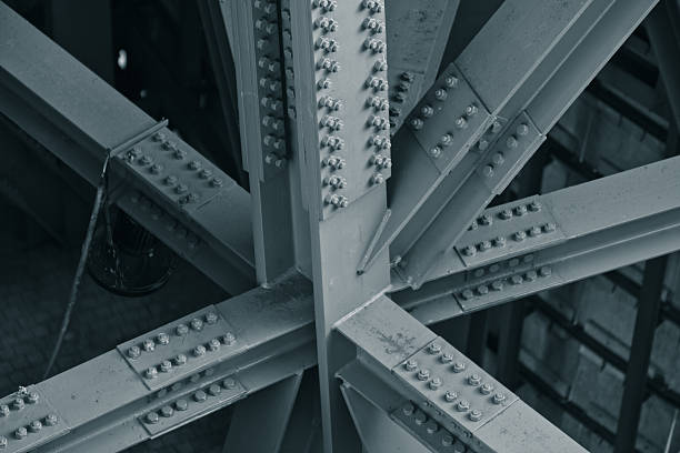
Connection Strategy: Bolted vs Welded and Why It Matters
Steel Structure Design Process: From Concept to Shop Drawings hinges on connection strategies, pitting bolted versus welded joints for performance and practicality.

Bolted connections shine in shop fabrication and field assembly, using high-strength friction grip (HSFG) bolts for shear transfer via clamp force, ideal for seismic zones due to ductility and inspectability.
Welded connections offer smoother force paths in moment-resisting frames, fusing members seamlessly but demanding skilled welders and NDT for quality assurance.
Site conditions sway the choice—bolted suits modular erection in remote areas, reducing weather delays, while welded excels in controlled shops for precision.
Cost-wise, bolted avoids welding consumables but requires more steel in plates; welded minimizes material but escalates labor. In the Steel Structure Design Process: From Concept to Shop Drawings, hybrid approaches blend both, bolting beams to columns and welding internals.
Fatigue resistance favors bolts in cyclic loads like bridges, as welds risk cracks without preheating. Corrosion protection differs—bolted uses galvanized hardware, welded needs coatings on toes. Code specifics, like AISC 360, mandate pretensioning for slip-critical bolts and fillet weld sizing per electrode classification.
Erection tolerances relax with bolts (up to 3mm), versus welded’s tight fits. Why it matters: poor connections fail first in disasters, as seen in earthquakes where ductile bolts dissipated energy.
The Steel Structure Design Process: From Concept to Shop Drawings thus prioritizes connections early, with finite element analysis verifying capacities.
Sustainability tilts toward bolted for deconstructability and recycling. Client education on trade-offs ensures alignment, preventing change orders. Mastering this strategy fortifies the Steel Structure Design Process: From Concept to Shop Drawings against real-world rigors.
read: Steel Structure Installation: Step-by-Step Erection Process
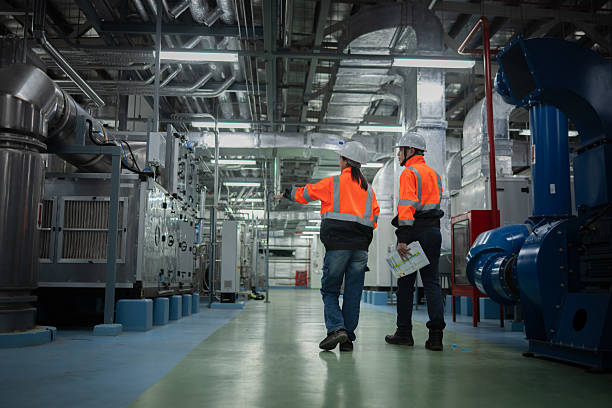
Shop Drawings & Detailing: What Clients Should Expect
Steel Structure Design Process: From Concept to Shop Drawings culminates in shop drawings and detailing, providing fabrication blueprints clients can trust.
Concept:
modern architecture, geometric pattern, building facade, glass windows, hexagon design, abstract architecture, contemporary building, urban structure, parametric design
These include plans, elevations, sections, member schedules, and BOMs, detailing cuts, holes, camber, and coping with tolerances like AISC standards (±2mm for lengths under 7.5m). Clients should expect 2D/3D views via Tekla or Advance Steel, enabling CNC machine feeds for precision.
Connection details specify bolt grades (A325/A490), washer types, weld symbols (AWS D1.1), and stiffeners, with notes on galvanizing or fireproofing. Anchor bolt plans layout base plates, embedments, and leveling nuts, critical for foundations. Assembly sequences outline erection logic, phasing for large projects.
Review cycles involve engineer approvals, clash checks via Navisworks, and client sign-offs, typically 2-4 weeks. Clients receive marked-up sets post-revision, plus NC files for fab shops. In the Steel Structure Design Process: From Concept to Shop Drawings, detailing uncovers issues like member clashes early, saving 10-20% in costs.
Quality hallmarks: material take-offs matching bids, tolerance callouts, and coating specs. Digital twins allow VR walkthroughs for visualization. Expect iterative RFIs for ambiguities, ensuring fabricators deliver match-fit parts.
Sustainability details cover recycled content and modular packs minimizing waste. Clients gain confidence knowing shop drawings bridge design to reality seamlessly. This final phase perfects the Steel Structure Design Process: From Concept to Shop Drawings, yielding error-free construction.
Steel Structure Design Process: From Concept to Shop Drawings empowers clients with transparent, robust deliverables. Steel Structure Design Process: From Concept to Shop Drawings ensures every project stands tall through systematic rigor and expertise.
Frequently Asked Questions (FAQ)
What are the first inputs required in Steel Structure Design Process: From Concept to Shop Drawings?
Inputs include site surveys, geotechnical reports, architectural plans, load data, and codes, forming the project’s foundation.
Why prioritize load considerations like dead, live, wind, seismic, and equipment loads?
They determine member sizes and safety factors, preventing failures under combined worst-case scenarios.
How does concept design define grid, spans, height, and stability systems?
It iterates layouts for economy and function, selecting bracing or frames based on height and spans.
Bolted vs welded connections—which is better in Steel Structure Design Process: From Concept to Shop Drawings?
Bolted for field ease and ductility; welded for rigidity—choice depends on site, seismic risk, and cost.
What details do shop drawings provide in Steel Structure Design Process: From Concept to Shop Drawings?
Fabrication plans, connections, BOMs, tolerances, and erection sequences for precise manufacturing.